


3D Scanning Overview
Over the years, technological advancements have provided limitless opportunities and possibilities for the industry. 3D scanning, being one of the most common w-ays to inspect and test objects, allow users to virtually capture and replicate any physical object in digital format. With many different techniques for conducting 3D scanning, industry leaders often turn to outsourced labs for increased accuracy of 3D scan dataset.
What is 3D Scanning?
3D scanning is a method of inspection for the structure and surface of a part or component. The term ‘3D Scanner’ is used to describe the device which is used to retrieve data on an objects’ form and appearance. 3D scanners can be classified as devices that can capture shape, size, measurements and appearance of an object with the use of laser, light or x-ray technology.

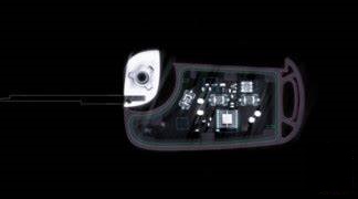
This accumulated data is further utilized in combination with a software to develop digitized three dimensional representation of the object.The 3D dataset is used for multiple different applications varying from animation and visualization to industrial testing and design. With endless possibilities of manipulating, designing, adjusting and visualizing an object in digital form, this technology has aided tremendously in bridging the gap between design and manufacturing. From industry perspective, 3D scanning is commonly referred to as a technology that is limited to inspection and analysis of an objects’ external structure and features. However, with the use of x-ray technology, users also have the option to access internal features of a component, using processes such as Industrial Computed Tomography (CT).
How 3D Scanning Works
3D scanning is a relatively quick and accurate method of displaying measurements of a certain object in digital format that is often collectively transferred into a computer aided design (CAD) model. 3D scanning offers many different techniques for testing and inspection purposes, subject to the size of the object being scanned. Since 3D scanning has the capability to scan anything from buildings, architectural interior, artifacts to intricate and delicate manufactured devices and components, it has proven to be a highly beneficial tool across many industries. 3D scanners capture the structure of a component, which progresses into digital form. In combination with a specialized software, this digital form (often raw data in point cloud format) is translated into a CAD file. This is done so to provide easy access and usable data for inspection purposes. For example, comparison to a CAD file, reverse engineering and dimensional analysis can be conducted only after the raw data has been converted with the assistance of a software. The most common methods for 3D scanning include 3D laser scan and white light scan.
Types of 3D Scanning Equipment
The following are the two most common types of 3D scanning technology utilized for industrial applications:
3D Structured light scanning (green light/white light scanning/blue light scanning) – also referred to as ‘structured light’. With the use of a ‘white light source’ (ex. Halogens), a pattern is exposed on the object being scanned. Measurements are recorded on the basis of deformation of the known pattern of light, as it comes in contact with the surface of object being scanned. The capturing sensors (ex. CCD cameras) have the ability to capture accurate data required for reconstructing measurements into 3D digital model.
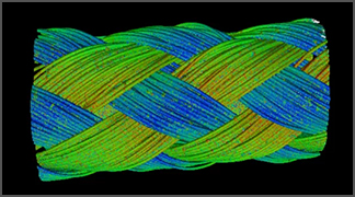
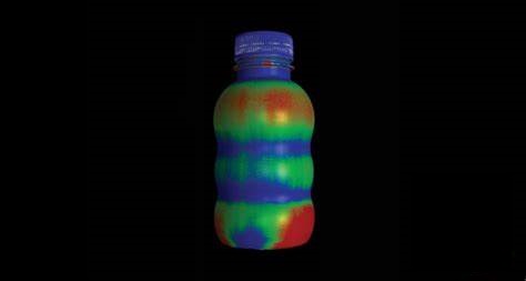
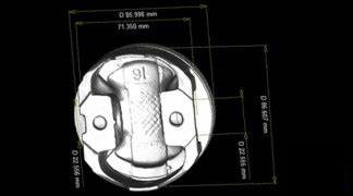
3D laser scanning – 3D laser scanning has the ability to capture the shape and size, and appearance of an object being scanned, by utilizing one or the combination of three different techniques: laser triangulation concept, time of flight scanning or phased based scanning. The scanning process develops a point cloud projected on the object. This data is reconstructed using a software into a 3D model. 3D scan results are utilized for quality control purposes across many industries. A 3D laser scan is one of the most utilized methods of replicating an object in full 3D form.
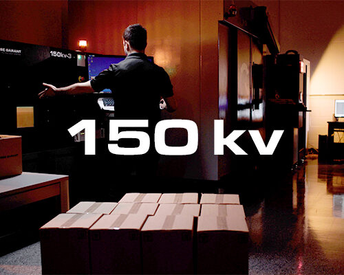
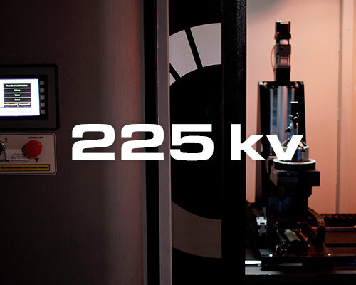
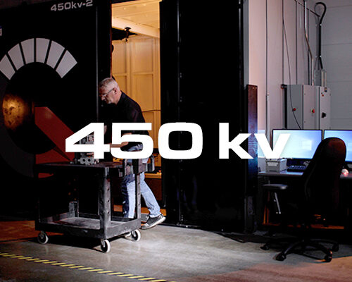
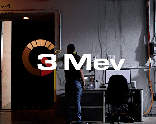
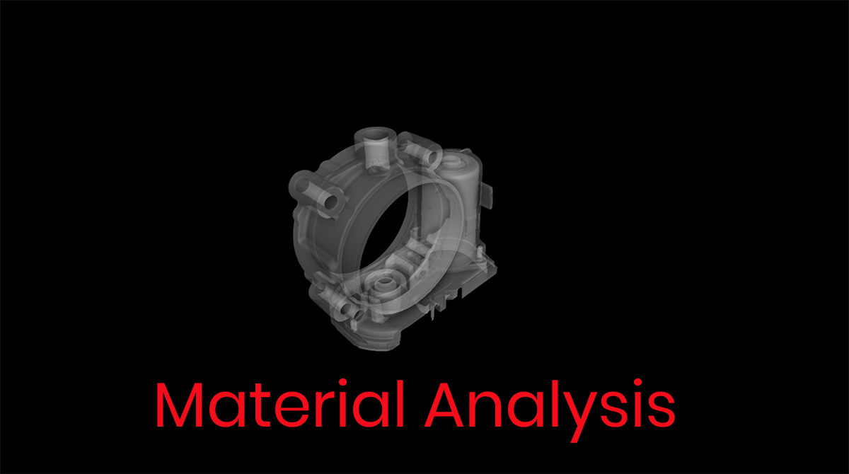
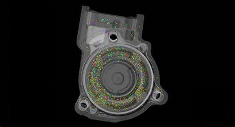
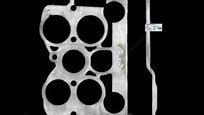
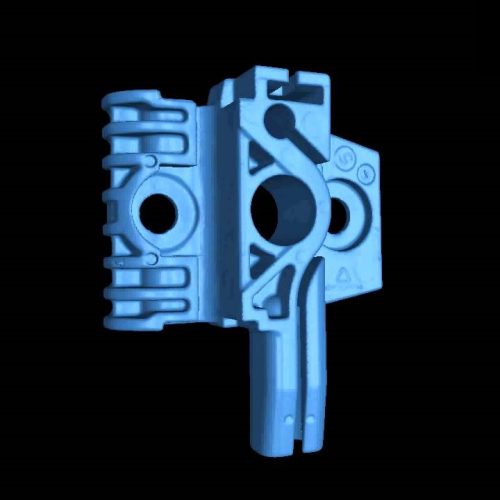
CT scanning – Computed Tomography (CT) scanning is a radiographic testing technique, utilizing an x-ray source to penetrate through materials and capturing 2D x-ray tomography slices at pre-determined increments for an object that is rotating 360 degrees. As the object rotates and 2D x-ray images are captured, a specialized software is used to reconstruct the 2D images and develop a 3D rendering of the object, which is available for further internal and external part analysis.
Benefits of 3D Scanning
3D scanning provides an array of multiple different technologies classified under one term. These technologies aid users with providing accurate part data, inspection and analysis. The most common benefits of 3D scanning are listed below:
- Providing access to dimensional analysis
- Accurate and quick part data
- Laser scan is nondestructive
- Assist in design and modeling of part
- Exceptional tool for prototyping to reduce costs and time
- Pre-production qualification and verification of part
- White light scanners are harmless to the human eye
- Identify failures and re-adjust design digitally
- Reverse engineering solutions
- Part to CAD comparisons for part accuracy and design verification
- Save time and money by eliminating extensive efforts in design and prototyping
- Beneficial in combination with advanced manufacturing
Applications of 3D Scanning
Although it can be utilized for many different applications such as developing a visual for video games and production of movies, 3D scanning is also commonly used for industrial applications. Depending on the project needs, 3D scanning can be most efficiently utilized during the pre-production stage of a manufacturing cycle, production stage and failure investigation. Following are the different areas where 3D scanning can prove to be an effective tool:
- Research & Development
- Design and prototyping
- Structural surface failures
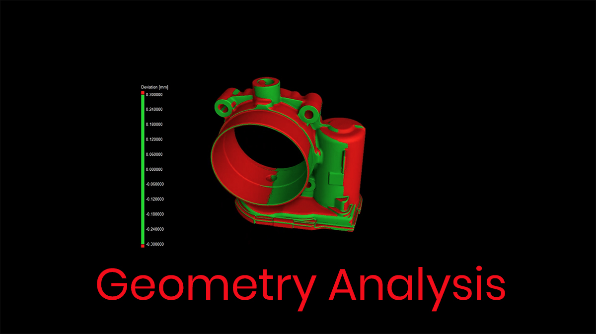
- Dimensional analysis
- Reverse engineering
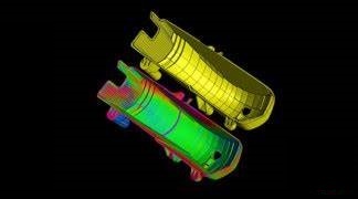
- Part to CAD comparison analysis
- Archive accurate data digitally
- Inspection and quality control

3D scanning Process
The 3D scanning process is different for each project, depending on the size limitations, 3D scanning technique utilized and the purpose of the project. However, a broad range of steps must be followed when approaching 3D scanning for the inspection of an object. These steps are presented below:
- Identify need for developing a 3D model
- Identify 3D scanning technique to be utilized according to the part (size/material – contact/noncontact)
- Identify 3D scanning software most accessible for project to process output of data
- Convert raw data into CAD format
- Perform reverse engineering, subject to project needs
- Comparison to CAD file, subject to project needs
- Perform inspection/ adjust design/ archive data
- Convert digital format into manufactured component, subject to project needs